Originally published in the October 2012 edition of Landscape Architecture Magazine
There is no such thing as a flat site (Fig 1). Terrain, slopes, and grading are an intrinsic part of site related projects, but many people struggle with representing terrain in a digital form. In the 7 years I’ve been teaching students and professionals to create models in SketchUp, the most common question I get is how to work from a digital site survey (for example from AutoCAD) with contours to generate a SketchUp model that integrates the site features, like buildings, walls, roads and walks into the terrain.
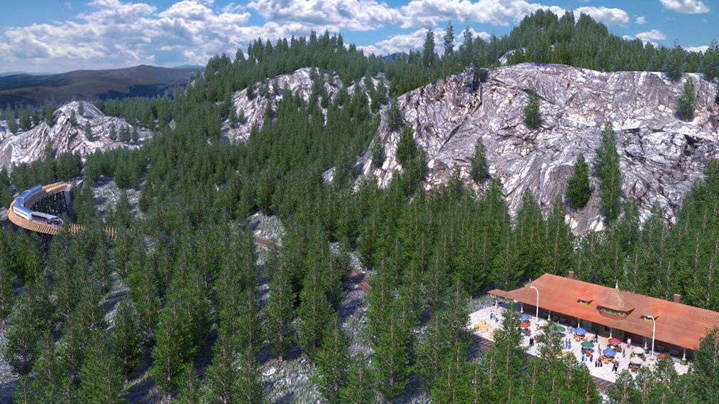
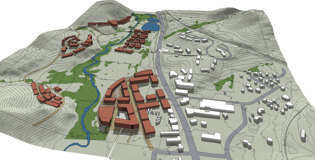
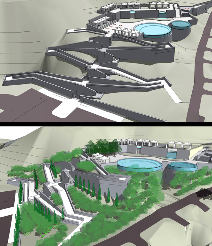
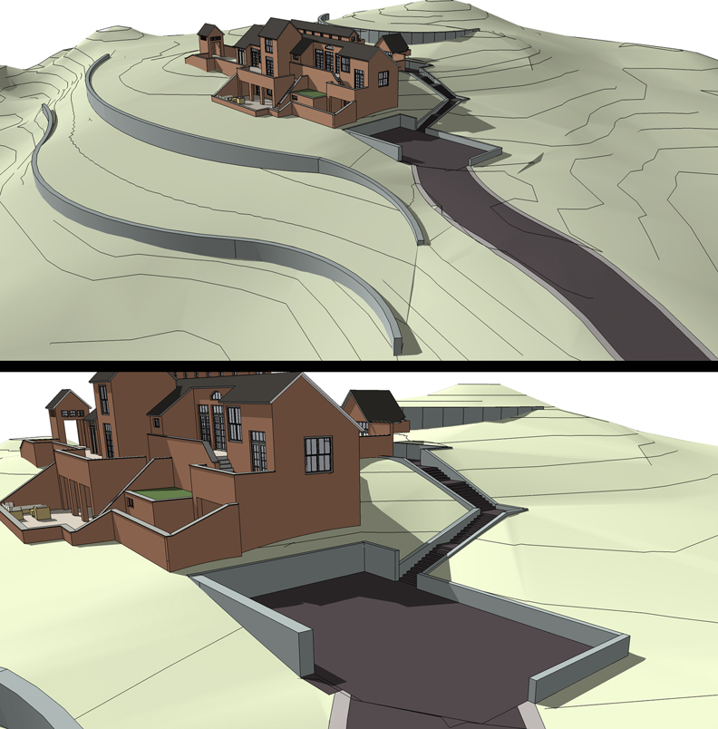
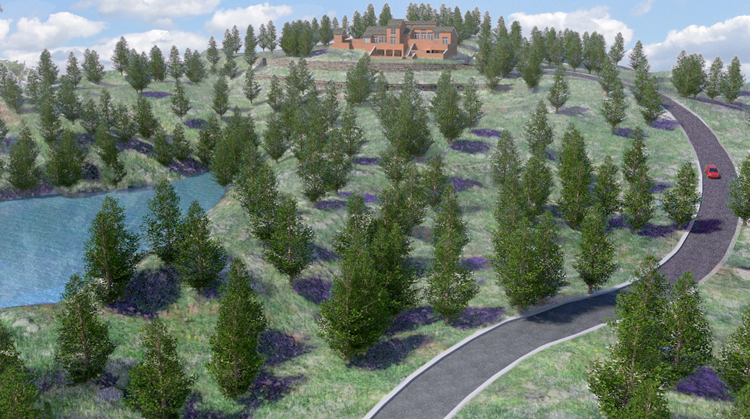
It’s actually not that hard. You’ll need to be working in SketchUp Pro, as the free version of SketchUp is unable to import DWG files from AutoCAD. You’ll also need to install several free ruby scripts—plugins that customize your SketchUp application and increase its capabilities. With a basic knowledge of SketchUp and the right tools, you should be able to convert a 2D contour map from AutoCAD into a digital elevation model in SketchUp in less than a day. Many different types of terrain models can be created from small residential scales to larger master plans (Fig 2 & Fig 3).
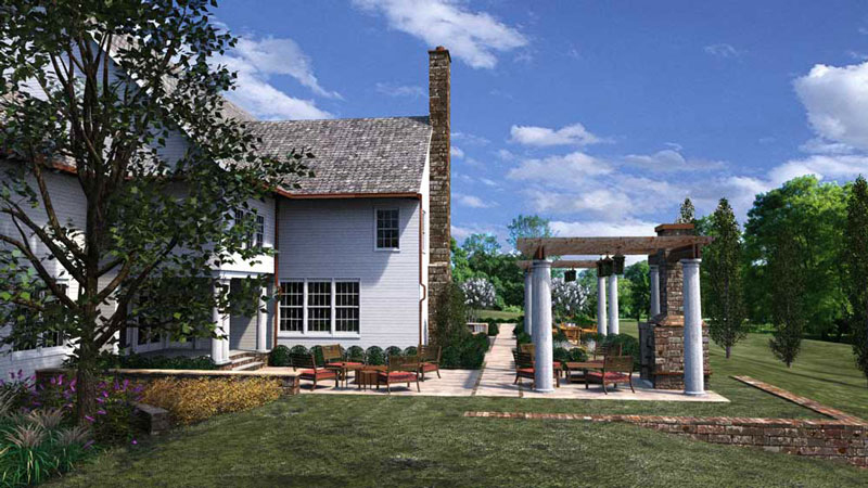
Such a model will give you a feel for how your design will actually look on the land. It will also make your proposal much clearer to a client who is not trained to read traditional grading plans (Fig 4). But be warned that SketchUp has some limitations as a tool for grading design. First is the accuracy of the generated terrain. SketchUp is able to create a general representation of the site and grades but is not a very good tool for fine grading. It does not have tools that can perform Cut/Fill calculations or automatically indicate percent slopes and spot elevations.
The process for creating SketchUp terrain models from AutoCAD plans outlined below assumes you have some basic knowledge of grading, AutoCAD (or similar Cad programs0, and SketchUp. There are nuances throughout the process that are not reviewed in this article. However, if you have those basic skills, you should be able to navigate this methodology.
SketchUp Tools and Plugins
Before you begin, it may be helpful to review a few basic tools that are included in SketchUp. The From Contour tool is used to generate a digital elevation model from imported contour lines or other lines with a Z-value. The tool stitches together contours, connecting vertices with flat, triangulated faces. It can also be used to re-grade around site elements like walls, steps, and other objects to merge them into the terrain you’ve generated from the contours. Another tool, Drape, let’s you project linework representing walks, roads and trails onto the terrain model you’ve generated. These Sandbox tools are a part of SketchUp, but they may need to be enabled if they’ve never been used. If you don’t know how to do this, google “enable sandbox tools SketchUp.”
You will also need to download and install four ruby script plug-ins before you start. All of them are available for free online.
Simplify Contours is an essential tool, available through SketchUp’s website. The Ruby Script removes about 50% or more of the points (also called vertices ) that compose a typical surveyed contour line. The Ruby selects vertices that are at shallow angles relative to each other and removes them. This limits the loss of the terrains profile. The greater the number of points or vertices, the greater the number of faces created when using From Contour on imported contour data. This will cause the terrain process to take considerably longer because SketchUp needs to process more information. Decreasing vertices makes it easier for SketchUp to complete functions like From Contour and Drape. Reducing the number of points that define a contour line reduces the accuracy of that line; however in most cases the difference is not noticeable.
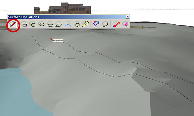
Tools on Surface, also called Surface Operations, allows you to draw lines and shapes directly on terrain (Fig 5). Its primary function is to supplement SketchUp’s Drape tool and fix incorrectly draped line work. An Offset function allows contours and outlines to be offset on the surfaces. The tool is available from SketchUcation (www.SketchUcation.com). Google “Sketchucation Tools on Surface”. Free registration is required.
Joint PushPull allows multiple surfaces to be extruded or depressed at the same time. For example, a road profile draped onto terrain can be selected and depressed creating a 6” curb. Google “SketchUcation Joint PushPull.
DropGC allows components representing vegetation and other objects to be dropped onto terrain, so that they are directly on the surface. This tool is essential for placing trees and other vegetation in one quick step instead of trying to place each onto the terrain individually. It is available from www.smustard.com
Additional Ruby Scripts
There are additional Ruby Scripts that are ideal for working with Terrain reviewed at the end of the article.
Preparing the File in AutoCAD
Before you open your grading plan in SketchUp, you will need to prepare it in AutoCAD (Fig 6).
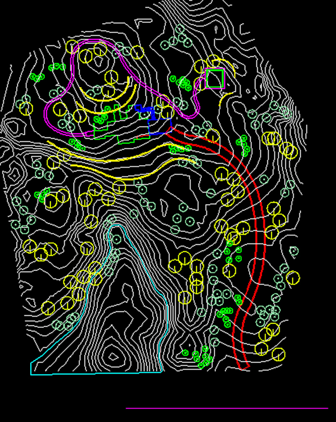
Check Z-values: All contour lines must have Z values, representing their elevations. In AutoCAD, select and List a contour line, and check the Z value. If it is 0 then the contour has no elevation and you will need to type in its elevation using the Properties menu. Pay particular attention to the proposed contour lines that you’ve created yourself. Surveyed contours typically possess Z elevations already, but it won’t hurt to check these too.
Your other linework—the roads, paths, walls, steps, and building footprints, should all have a Z value of zero. If not, they should be flattened in CAD. Freeze the contour data so it is not visible, then type “flatten” in AutoCAD and select the site plan linework. AutoCAD will ask to include Hidden Lines as part of flatten. Answer “no.”
Close Polylines: You will also want to insure that all linework areas are closed lines or polylines.. Closed areas are easier to drape on the terrain. It is possible to fix flaws created by draped lines that are not closed however, this can be a time consuming processes. Better to have it done correctly in AutoCAD.
Minimize Contour Data: Minimize the amount of contour data imported into SketchUp. The more contour lines the longer the process can take and having more data does not necessarily make a more accurate terrain model. SketchUp produces the terrain model using the Z-value of the line—it does not require you to build from contours at a regular interval. So, if you are showing a hill with a continuous slope, it is not necessary to show every contour that makes up that slope. Just showing the contours at the top and bottom should be enough.
Separate Different Layers into Separate Files: Instead of importing your whole AutoCAD file into SketchUp, it’s best to isolate different types of information and save it in separate files using the WBLOCK command. I typically create separate CAD files for contours, roads, trails, walks, walls and steps, building footprints, and vegetation—which were each originally drawn on separate layers in CAD. Each one of these files will be imported into SketchUp one at a time. This insures that only relevant linework is inserted into SketchUp, and adding the data to your model in stages makes it easier for SketchUp to process (Fig 7).
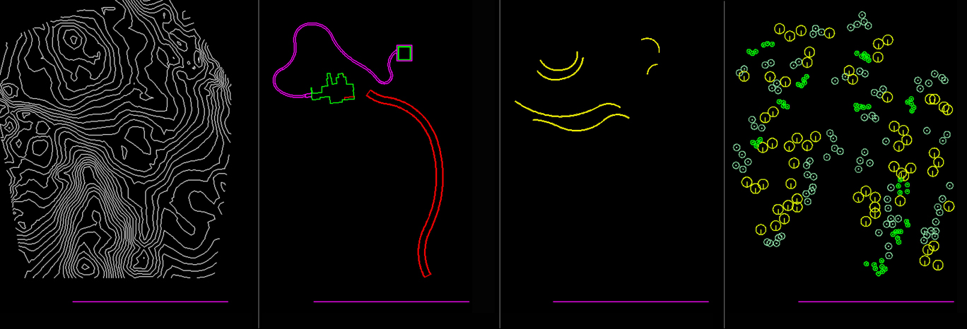
In order to align each file in SketchUp, you will need to create a benchmark that can be included in each file. Create a new layer in AutoCAD called Benchmark and make it the active layer. Then, draw a horizontal line that does not cross any of your other linework (for example in the bottom right of the plan).
Creating the Model
Importing DWG Files: Now it’s time to import the files into SketchUp. Always start by importing the Contour information. To import DWG files, in SketchUp go to File import, From the Browser menu select DWG at bottom. Navigate to the location of files you saved using the WBLOCK command and select the contour file. Once you’ve imported the contour file, look to make sure the bench mark line is present in the imported linework (it might be hidden behind one of the Green or Red Axis line). This will save you a lot of headaches later. If all the contour lines are a group, explode them.
Simplifying Contours for Easier Processing: Select all the contours and use the Simplify Contour Ruby script on to remove vertices. Once the plugin is selected, SketchUp will ask for an Angle. This represents the angle of ‘bend’ between points (vertices) along a contour line. The default of 10 usually works fine. SketchUp will remove points that create angles of 10 degrees or less. The result is some contour lines will be deleted while others will be straightened slightly as some points are removed. If too many contours are deleted, undo the result and try Simplify Contour again. This time try adjusting the angle down in the hopes that SketchUp will not delete too many contours. If this process does not work, create a terrain without using Simplify Contour. However the rest of the process of draping and working with the terrain itself will take longer and SkethchUp might function at a slower rate due to having to process a greater amount of information.
Create Terrain from Contours: Select all the contours again and select From Contours on the Sandbox menu. This will stitch the contours together, creating the triangulated irregular network (of faces) or TIN. The created surface is a single group (Fig 8).
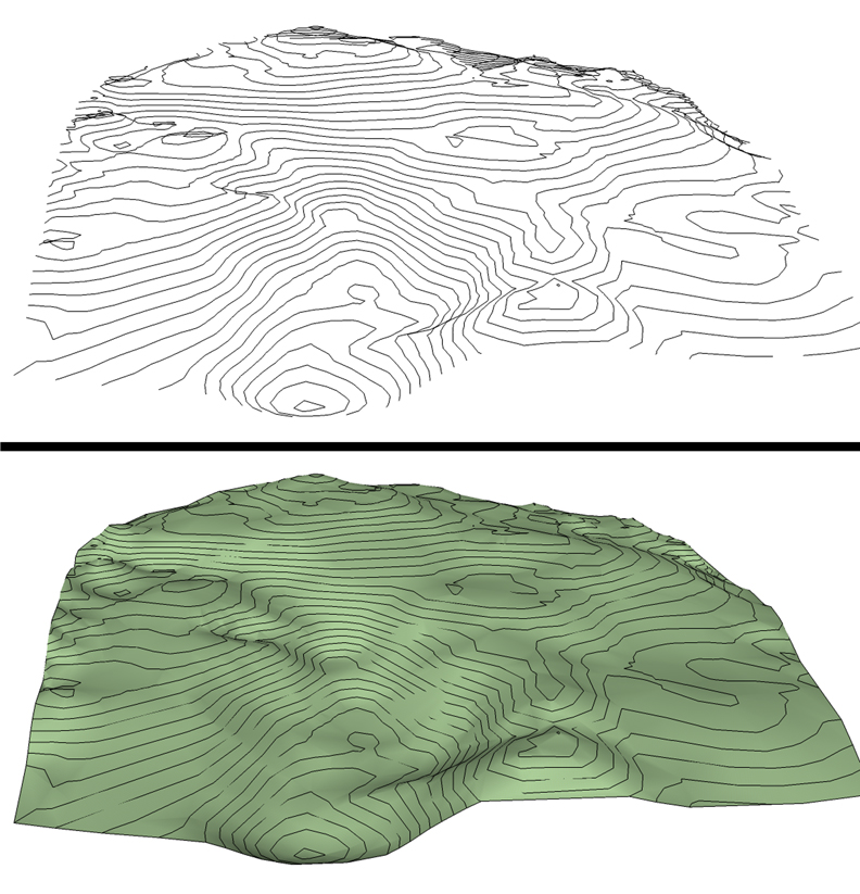
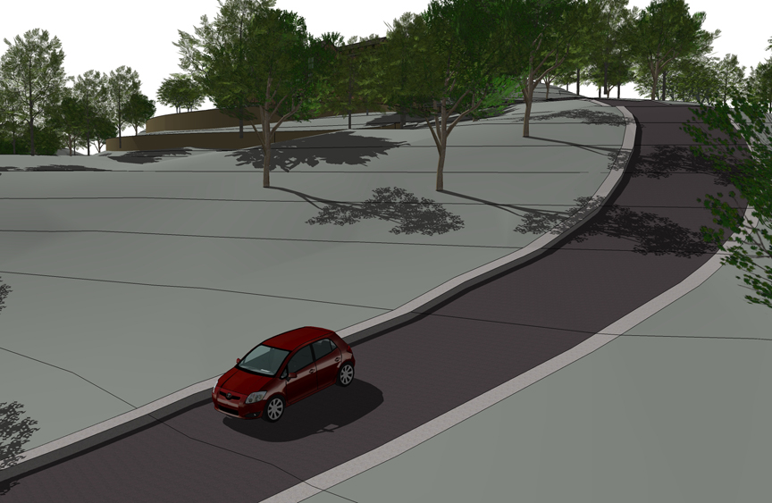
Overlaying roads, trails, and other linework on the terrain: Import each of these layers individually to cut down on processing. When you import the road linework, you’ll notice it is below the TIN. This is because the imported linework has no elevation data. Use the benchmark lines to align the information, and then move the linework directly upward over the terrain model. You can lock the direction of movement by using the up arrow on the keyboard when using the move tool. To drape the linework onto the terrain, select the linework. Activate the drape tool. Hover the drape tool over the terrain until it becomes selectable (you’ll see it is highlighted in blue). Then, left click to activate the operation. The roads should now be draped onto the terrain. The process is identical for trails, planting areas and similar hardscape (Fig 9).
Painting the Draped Layers: Interested in painting the road’s surface? Enter the TIN / Terrain Group instance, by double clicking on the terrain surface. Select the area with the outlined road. If Drape worked correctly the road surface should be its own discreet surface. If drape did not subdivide the road surface, use Tools On Surface to fix this issue. Using the Line on Surface tool draw an edge across the intended road surface, dissecting it in half. The typical result is that half the road will now be correctly subdivided. Continue to further subdivide the road with the Line on Surface tool until the surface is correctly subdivided. You can go back and erase all the extra lines after this is completed. You should now be able to apply an appropriate color to the surface. In this case, I’ve applied an Asphalt color to the road area.
Extruding Surfaces to Create Curbs: If you wish to create a depressed road with a curb, select the road surface and click Offset from the Tools on Surface menu. The selected road surface can be offset inward 6 inches creating a curb outline. Next select the road surface, right click over it and select Joint Push Pull. Depress the road 6 inches (Fig 10).
Grading Walls, Steps and Structures into the Site: Most site plans will require that walls, steps and similar objects like buildings be integrated into the terrain, not just draped on top of it. The process is simple but does require you to think through the integration as a grading exercise if you haven’t already.
First, the wall, steps or building are modeled, giving them extrusion and volume. Next, they are aligned and placed onto the terrain. This is where having proposed grades and spot elevations is useful, as it allows these objects to be placed based on more accurate grading parameters. For example, the building can be elevated based on its finished floor elevation. Steps and walls can be positioned based on bottom of wall or step elevations. If you are unsure about the correct position (it has not been figured out), the placement of these elements on the terrain to your best judgment.
Next, go to View - Hidden Geometry and make the hidden geometry visible. This reveals the many hidden lines that make up the terrain model, so that you can select individual faces of the terrain. Delete terrain faces around the object that will be re-graded into the surface (Fig 11).
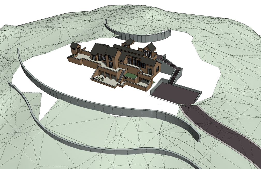
Select the terrain model group and enter the group instance by double clicking on the terrain itself. Using [SOME SPECIAL TOOL?], draw edges and arcs along the surface of the walls, steps or buildings. These lines represent the location where newly generated grades will meet the object. Be conscious of what lines and arcs are added and again, consider this in terms of a grading exercise trying to achieve the most realistic result for the object (Fig 12).
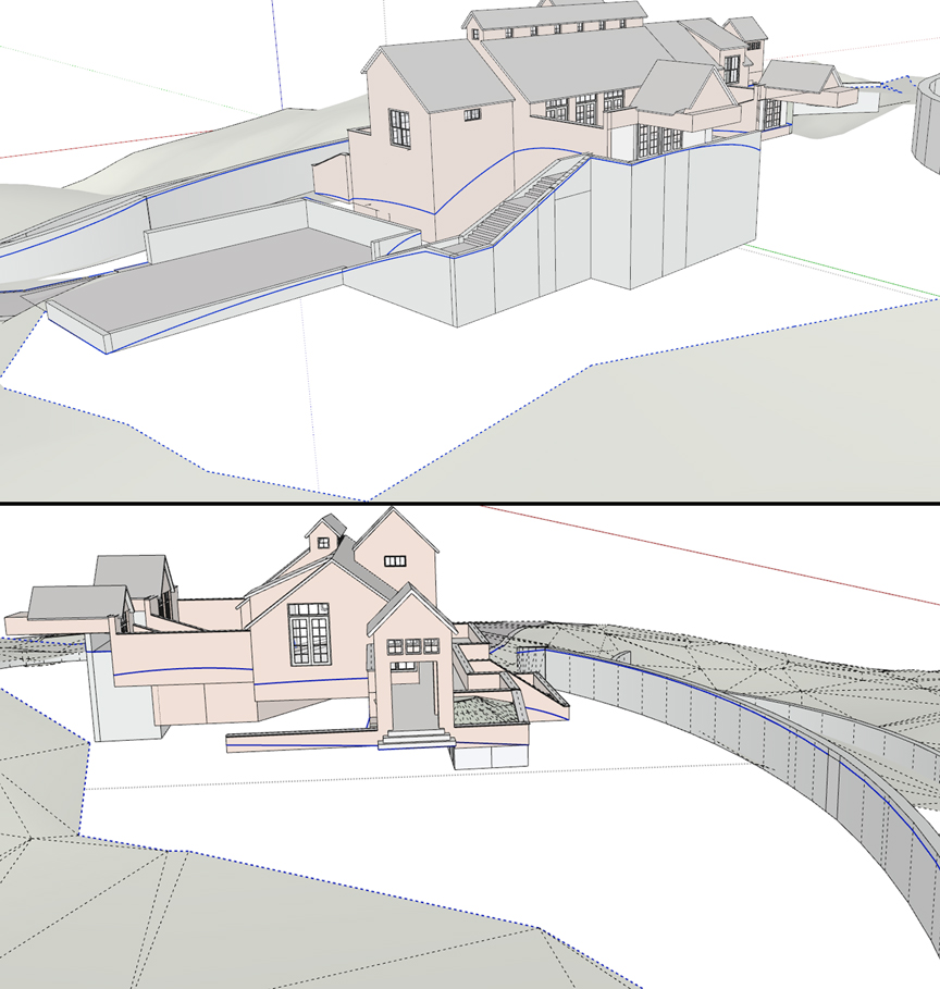
Select all these new lines and the edges of the adjacent terrain, then activate From Contour on the Sandbox menu. This will result in the terrain and object being integrated and graded. It might be necessary to clean up some of the excessive created faces. Don’t hesitate to undo and retry the process until the desired results are reached (Fig 13).
The Drop tool and Converting Vegetation Blocks to 3D Components
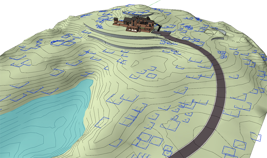
Vegetation and other site amenities, like pedestrian lights and furnishings, can be quickly and easily placed onto the terrain. But these features are typically imported as 2D blocks rather than linework, so the drape command will not work on them.
Import the file containing these blocks, align it using the benchmark and move the blocks up over the terrain. Explode the group containing the blocks, but be sure not to explode the individual blocks themselves.
It is recommended that you save the file first before performing the next step as it is not possible to undo this step. Select the blocks, right click over one of them and select Drop at Intersection from the right-click context menu Once dropped, each block will hug the terrain (Fig 14). If Drop does not work it is because an object other than a component or group was selected. Sometimes it’s best to perform Drop on a limited number of blocks to insure the process works.
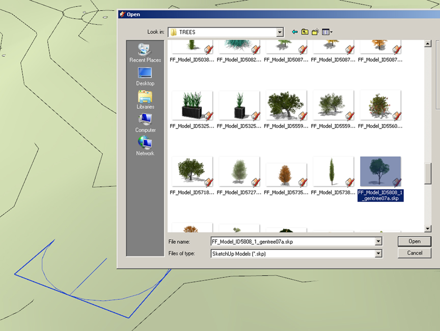
Replace the blocks with 3D components by selecting and right-clicking over a block. This will bring up the right-click context menu. From the options, select Reload. Navigate to your component folder and select a 3D component to replace the block. For example, you can select a 2D block representing a tree and then reload a 3D tree to replace it. All versions of that 2D block will be replaced with a 3D tree (Fig 15 & Fig 16). Repeat this step for every block and object type.
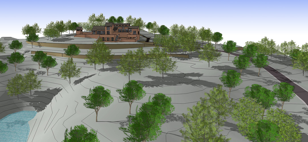
The model is complete and ready to be rendered (Fig 17).
Additional Ruby Scripts and Software for grading:
The tools laid out above will provide some basic functionality. But there are additional plugins that can help streamline the process. These tools are not free but solve some of the issues that SketchUp has when working with the base method; for example, by creating finer and smoother grades.
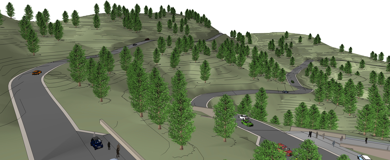
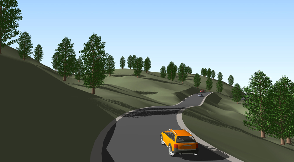
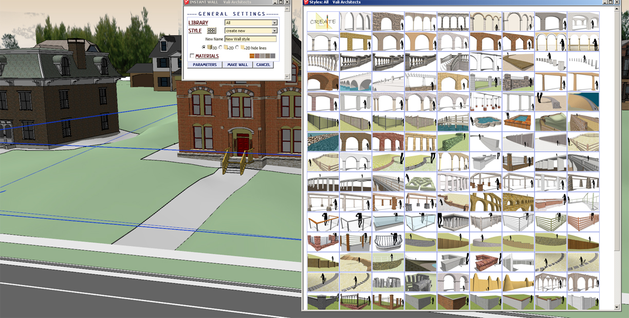
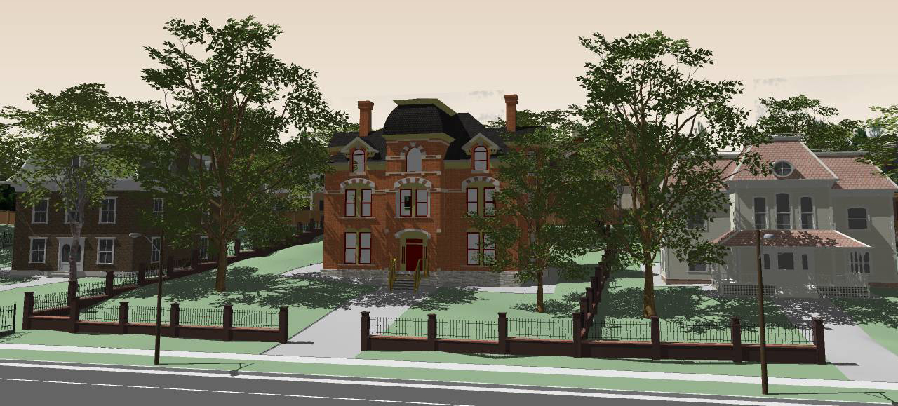
The Ruby Script Instant Road by Vali Architects (www.valiarchitects.com - cost $25) allows for draping a single face representing a road onto terrain (Fig 18 & Fig 19). The Plugin grades the road onto the surface creating a much smoother and realistic surface in comparison to the Drape tool. Instant Walls is an excellent tool allowing for the creation of walls, colonnades, fences and more by simply drawing a line, series of lines or arcs on surfaces, selecting the drawn edges and with one click converting them into the chosen element (Fig 20). These auto-generated structures will hug the terrain once created (Fig 21).
Other scripts by Vali include Instant Roof and Instant grade, which are worth exploring as they are quick shortcuts to creating detailed structures and integrating site elements into terrain.
A ruby script called Artisan created by the civil engineer Dale Martins is a series of tools bundled in a single menu that allow you to work with complex forms and shapes common in terrain modeling. These tools offer alterative to the some of the clunky counterparts found in the Sandbox menu. For example, the Artisan Sculpt Brush provides an excellent way to extrude or depress terrain creating swales, hills or other landforms by simply dragging the tool across the terrain surface. The strength of the tools extrusion is easily adjusted using the arrow keys on a keyboard. Other Artisan brushes make it quick to select terrain surfaces, level areas of terrain, or select surface vertices. Not to mention the many other tools it includes to further refine organic forms and shapes making Artisan is indispensible. The tool cost $39 and can be purchased at www.artisan4sketchup.com. There is an excellent post by SketchUp on their offical blog about Artisan: http://sketchupdate.blogspot.com/2011/03/organic-modeling-with-artisan-plugin.html
There are more tools beyond these as well. For example, it is possible to create terrain from point / cloud data using the right Ruby Script (ask on SketchUcation is this is what you need). Additional Ruby Scripts provide the means for further smoothing out terrain and generating new contour lines from any adjusted grading done to the model.
Daniel Tal is a landscape architect and Author of the forthcoming book, Rendering In SketchUp: From Modeling to Presentation for Architecture, Landscape Architecture and Interior Design (due on book shelves in February 2013). The book reviews how to create photorealistic graphics in SketchUp. Daniel is also the author of Google SketchUp for Site Design. To find out more about Daniel and related services go to www.ambit-3d.com or contact Daniel at ambit3d@gmail.com
Image Courtesy
Daniel Tal
www.danieltal.com
- Cover Story
-
 SketchUp Can Help You Win Interior..
 -
 Best Laptops for SketchUp
 -
 How to Resize Textures and Materials..
 -
 Discovering SketchUp 2020
 -
 Line Rendering with SketchUp and VRay
 -
 Pushing The Boundary with architectural
 -
 Trimble Visiting Professionals Program
 -
 Diagonal Tile Planning in SketchUp
 -
 Highlights of some amazing 3D Printed
 -
 Review of a new SketchUp Guide
- Sketchup Resources
-
 SKP for iphone/ipad
 -
 SKP for terrain modeling
 -
 Pool Water In Vray Sketchup
 -
 Rendering Optimization In Vray Sketchup
 -
 Background Modification In sketchup
 -
 Grass Making with sketchup fur plugin
 -
 Landscape designing in Sketchup
 -
 Apply styles with sketchup
 -
 Bedroom Making with sketchup
 -
 Review of Rendering Software
 -
 Enhancing rendering for 3d modeling
 -
 The combination of sketchup
 -
 Exterior Night Scene rendering with vray


